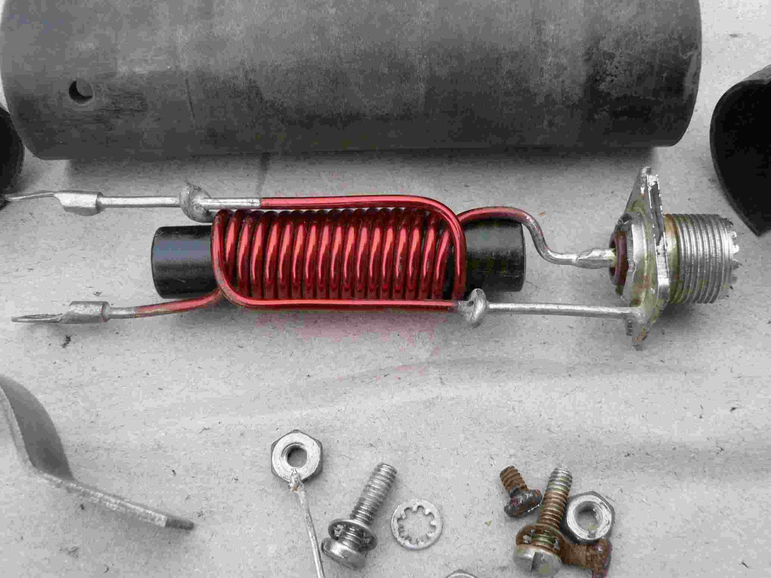
Here now the reworked original cushcraft balun.
It was an awful view after opening the balun. I found not
only the spider cocoons. Also ants
inside and they brought a
lot of sand and mud into the balun. I really don't know
some days of clammy weather. Nearly half size of coil laid in that mud. Also the ferrite core stick only 3/4 inside
the coil. After carefully cleaning all it looks quite good now and I will use the balun for the ATB-34.
I made a short balun test.
I used my MFJ-259 HF/VHF Antenna/SWR/RF Analyzer and a 50-Ohm dummy load. See pictures! I checked
the frequency response from 10 - 30 MHz.
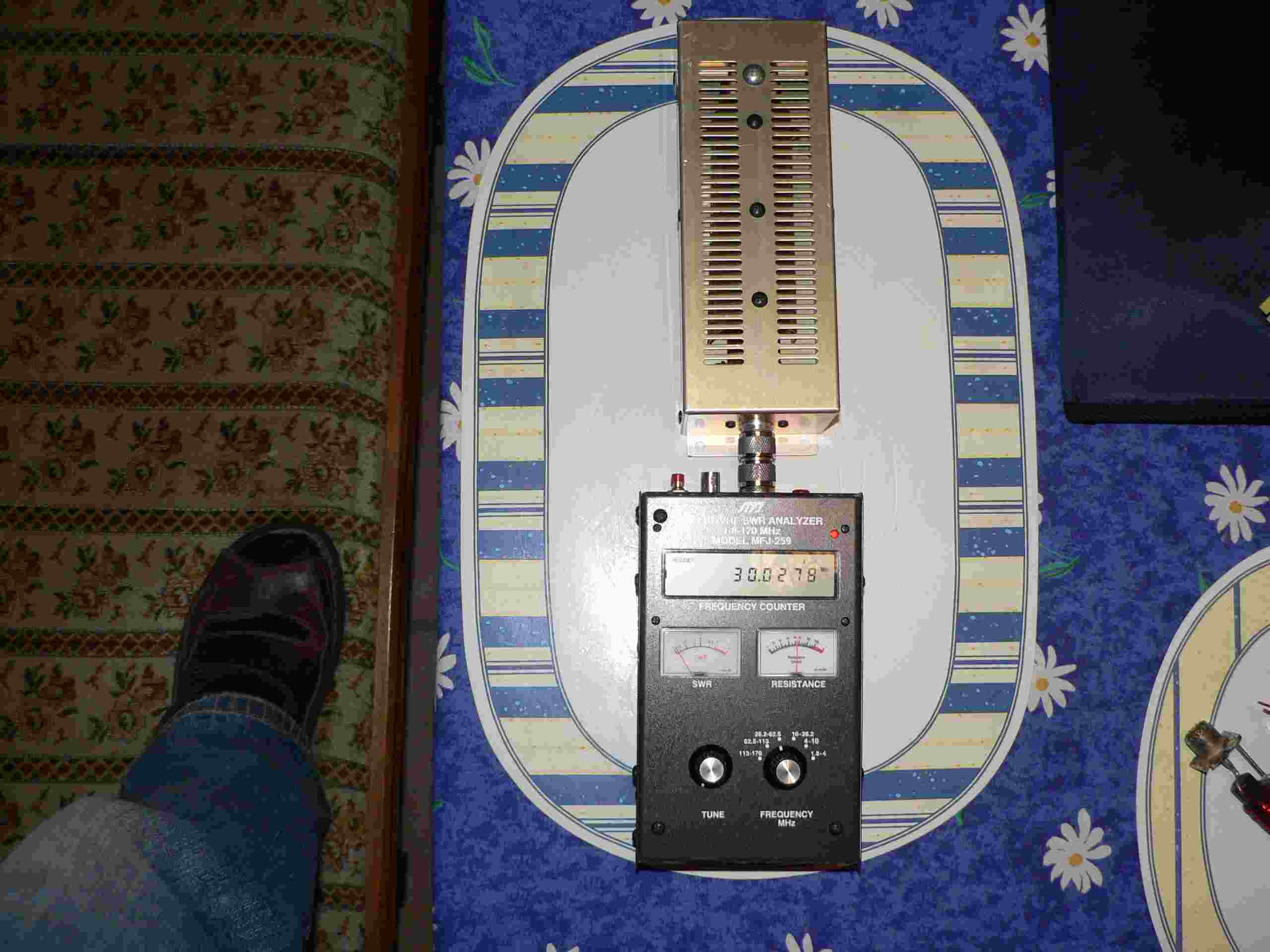
1st, I checked the VSWR of the dummy load. By direct
connection of the Analyzer to the 50-Ohm dummy I read
50-Ohm on the resistance meter and 1.1 on the SWR meter. No
changes by tuning from 10 too 30 MHz occur.
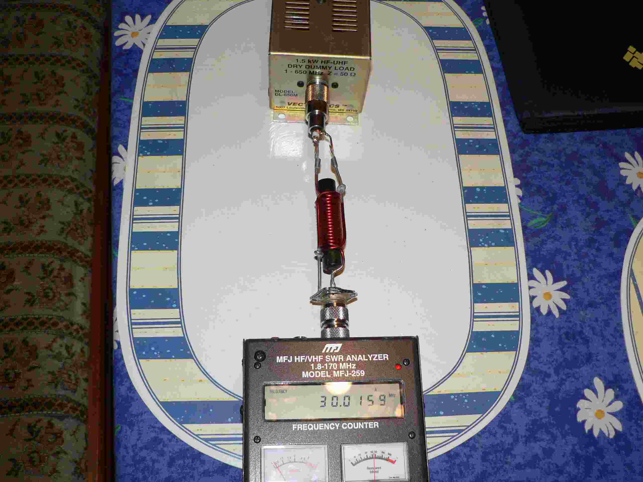
2nd, I connected the balun between the Analyzer and the 50-Ohm
dummy. Results are exactly the same like in
the 1st test.
3rd, I made exactly the same test with the HyGain BN 1000 Balun. Here I found that the SWR from 21 MHz up is 1.2!
And from 10 to 21 MHz the SWR is just a needle's breadth higher than the Cuschcraft balun.
Les than 10 MHz and up over 35 MHz the SWR is increasing
and also the resistance changed below 50 Ohms.
Cushcraft balun:
7 turns trifilar winding, lenght 45mm, core length 62mm, core diameter 12mm, wire AWG 12 or 13, (1,8-2,05mm)
HyGain Balun:
9 turns trifilar winding, length 55mm, core lenght 70mm, core diameter 12mm, wire AWG 12 or 13 (1,8-2,05mm)
Shematic:

So the results I found on the Cushcraft balun are better than I expected, therefore I will use the balun like it is.
________________________________________________________________________________________
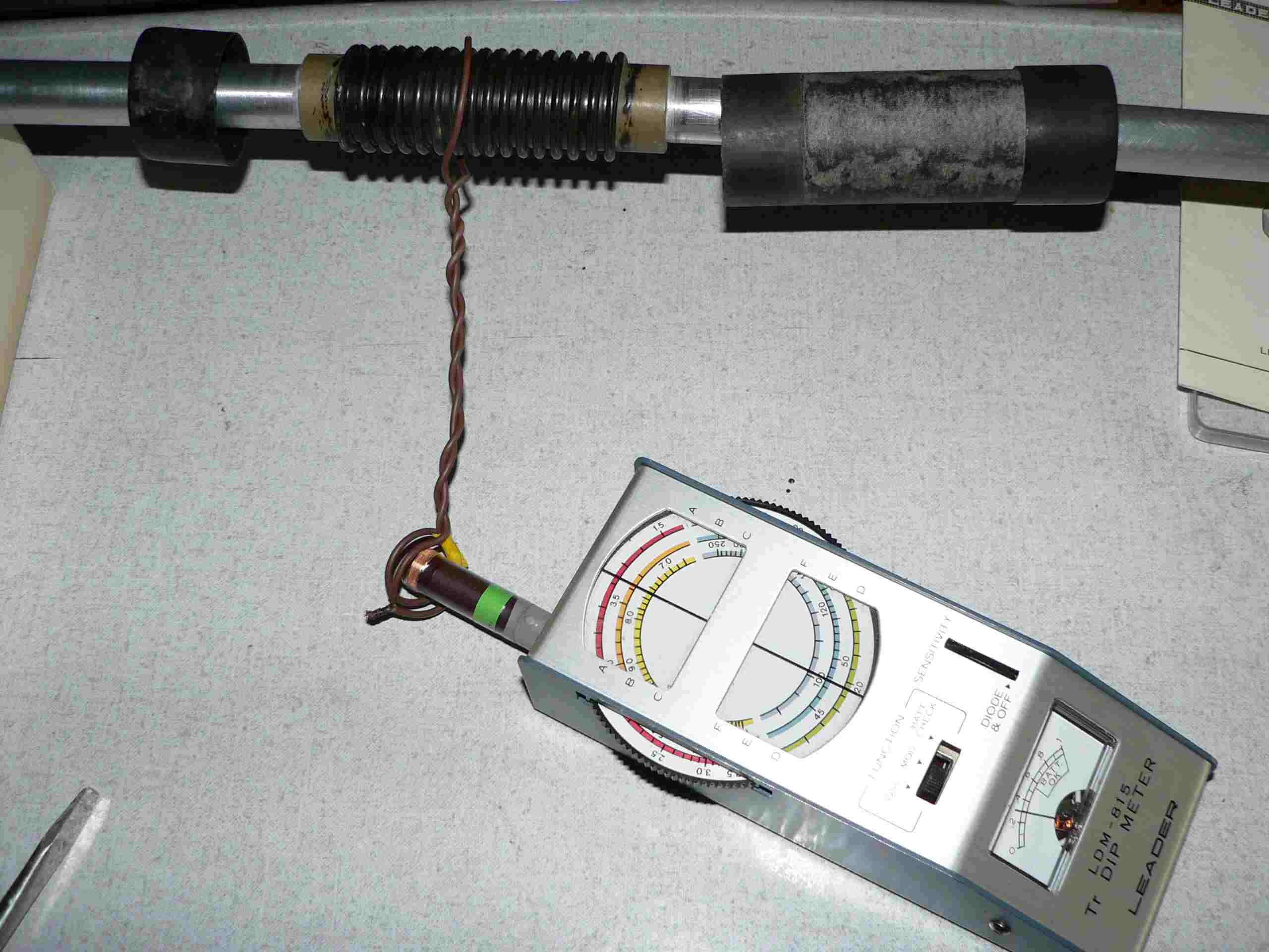
Checking all traps before assembling the elements.
The Cushcraft traps are simple mechanical construction (see
pic. 6). A fibre tube carrying the coil and the element tubes.
The capacitor made from a piece of coax
and rubber end caps used to seal the coax against dampness.
Test: How to do?
Simply because the traps are tuned
circuits; I used my old transistor dip-meter to check the resonant frequency of the traps.
I got clear resonance dip's by using a link coupling. One turn around the trap coil and two turns on the dip-meter coil.
Reflector 15m trap only loose link coupling is needed
Driven element 10m trap Driven element 15m trap
No differeces in measurement results found if the link coupling is direct on the coil or over the plastic slipcover.
Here are the found trap resonance frequencies:
| reflector el. resonance 15m trap left | 19,9 mc (20,5 mc) | reflector el. resonance 15m trap right | 19,9 mc (20,5 mc) |
| driven el. resonance 10m trap left | 26,5 mc (27,1 mc) | driven el. resonance 10m trap right | 26,5 mc (27,1 mc) |
| driven el. resonance 15m trap left | 19,5 mc (20,1 mc) | driven el. resonance 15m trap right | 19,5 mc (20,1 mc) |
| director el. resonance 10m trap left | 27,0 mc (27,6 mc) | director el. resonance 10m trap right | 27,0 mc (27,6 mc) |
| director el. resonance 15m trap left | 19,1 mc (19,7 mc) | director el. resonance 15m trap right | 19,1 mc (19,7 mc) |
| During measuring the dip frequencies | all is checked with | the a receiver: | |
| Scale-reading precision for the test: | within 10 kc | Repeat accuracy for the test | within 50 kc |
I suppose, that the exact 'only' trap (coil and capacitor only) resonance frequency is about 500 kc - 700 kc higher!
Like you see on the pictures, I've done the measuring on the complete assembled traps. Additional inductance and
capacity from the element tubes cause a lower resonant frequency.
Last I checked the Q of the trap circuits by comparing the clear of the dip's on the dip-meter with a homemade
LC-circuit. Nearly the same dimensions of the coils are used, but an air-capacitor instead of the coax-capacitor. Also I
used the same link coupling. Only very minor deviation found in the clearness and depth of resonance dip's on the meter.
I conclude from the fact that the Q of the traps is very good.
And now, make a beam antenna:
 All assembled now and stored in the back of the garden.
We will bring the antenna up if the the next suny day let's work outside.
... soon more
Zurück zur Hauptseite/go main page